Mock-up Azure VMware Solution in Hub-and-Spoke topology – Part 1
Overview
If you are using Azure VMware Solution to run your VMware workloads on Azure, you might wonder how to connect it with other Azure resources in a secure and efficient way. One option is to use a hub-and-spoke network topology, which is a design pattern that consists of a central virtual network (the hub) that acts as a gateway for multiple spoke virtual networks. In this blog post, we will investigate how to make Azure VMware Solution work with hub and spoke topology and what are the challenges of this approach.
By using a hub and spoke topology with Azure VMware Solution, you can achieve several benefits such as improved security & isolation of cloud hosted workloads. However, you also need to consider some challenges such as complexity, latency, bandwidth limitations, routing complexity, firewall rules management, etc. Therefore, it is important to plan your network design carefully according to your specific requirements.
The official Azure documentation already provides a set of scenarios related to network connectivity for Azure VMware Solution. You can find them here. In this blog post series, we will reproduce, step-by-step, a mock-up scenario very close from the Network virtual appliance in Azure Virtual Network to inspect all network traffic one.
The components and network design described in this blog post are only for demonstration purposes. They are not intended to be used in a production environment and does not represent Azure best practices. They are provided as-is for mock-up and learning purposes only.
Materials
To illustrate this blog post series, I created a GitHub repository to host Terraform code to reproduce each step of the process documented here.
Using this Terraform content provides a repeatable way to deploy the same environment on Azure but all the steps described in this blog post can also be reproduced using the Azure Portal or Azure CLI.
Azure VMware Solution deployment
The deployment and configuration of Azure VMware Solution is out of the scope of this blog post. We consider that the AVS environment is already deployed and configured. We will cover the mandatory settings for Hub and Spoke topology in a section of this series.
Stage 0 – Basic setup
As a first step, we will start our lab setup with some very basic components like:
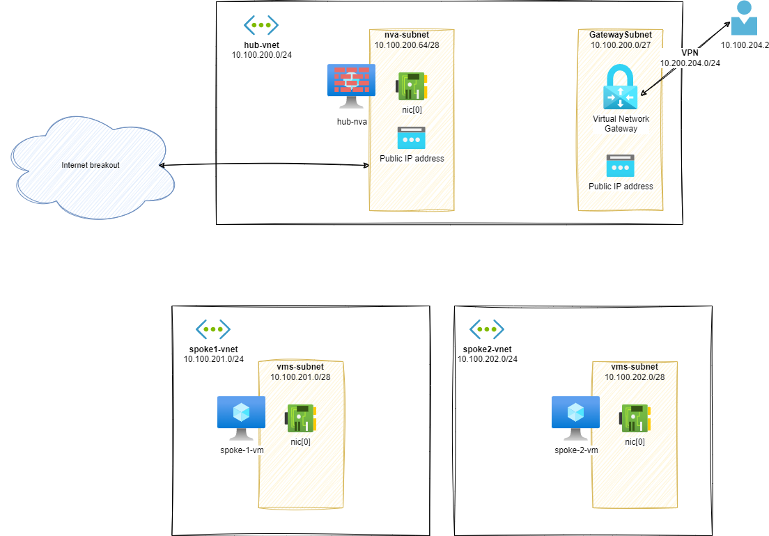
- A hub vNET:
hub-vnet- A VM (to be NVA)
- A Virtual Network Gateway
- I choose a VPN one to simulate an On Premises behavior without having a costing Express Route circuit at my disposal
- 2 spokes vNET:
spoke1-vnetandspoke2-vnet- With a spoke VM in each one
- A P2S VPN Subnet will act as an On-Premises based workload
Routes analysis
Once this setup is built, we can have a look at routing configuration between components:
Effective routes on hub-nva.nic[0]:
1az network nic show-effective-route-table \
2    --ids /subscriptions/<sub-id>/resourceGroups/nva-testing-RG/providers/Microsoft.Network/networkInterfaces/hub-nva-nic \
3    -o table
4# output
5Source                 State    Address Prefix    Next Hop Type          Next Hop IP
6-------------------- - ------ - ----------------  -------------------- - ------------ -
7Default                Active   10.100.200.0/24   VnetLocal
8VirtualNetworkGateway  Active   10.100.204.0/24   VirtualNetworkGateway  20.16.121.157
9Default                Active   0.0.0.0/0         Internet
From UI:![Effective routes on hub-nva.nic[0]](https://vuptime.io/images/avs-nva/stage0/effectives-routes-hub-nva.png)
Effective routes on spoke-1-vm.nic[0]:
1az network nic show-effective-route-table \
2    --ids /subscriptions/<sub-id>/resourceGroups/nva-testing-RG/providers/Microsoft.Network/networkInterfaces/spoke-1-vnet-vm-nic \
3    -o table
4# output
5Source    State    Address Prefix    Next Hop Type    Next Hop IP
6--------  ------ - ----------------  -------------- - ------------ -
7Default   Active   10.100.201.0/24   VnetLocal
8Default   Active   0.0.0.0/0         Internet
From UI:![Effective routes on spoke-1-vm.nic[0]](https://vuptime.io/images/avs-nva/stage0/effectives-routes-spoke-1-vm.png)
As you can already guess from both diagram and routes listing, the communication between distinct vNets is not possible:
Example, from hub-nva to spoke-1-vm:
1ubuntu@hub-nva:~$ ping 10.100.201.4 -c3
2# output
3PING 10.100.201.4 (10.100.201.4) 56(84) bytes of data.
4-- - 10.100.201.4 ping statistics ---
53 packets transmitted, 0 received, 100% packet loss, time 2036ms
If we try to communicate between spokes, the result will be the same: their is no connectivity between vNets.
Additional information about Azure Routing
If you need to learn more about network & routing in Azure, I strongly recommend you to read the following amazing blog posts:
- Azure Networking is not like your on-onprem network by Jose Moreno
- NIC Routing & Azure routes by Cynthia Treger
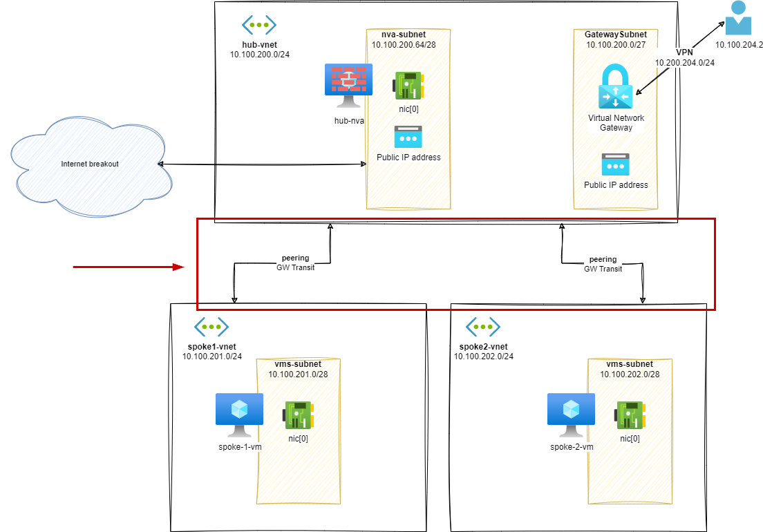
Stage 1 – Peering spokes
In this stage, we will add a peering between spoke1-vnet, spoke2-vnet and hub-vnet to enable communication.
Routes analysis (s1)
Once this setup is built, we can have a look at routing configuration between components:
Effective routes on hub-nva.nic[0]:
 1az network nic show-effective-route-table \
 2    --ids /subscriptions/<sub-id>/resourceGroups/nva-testing-RG/providers/Microsoft.Network/networkInterfaces/hub-nva-nic \
 3    -o table
 4# output
 5Source                 State    Address Prefix    Next Hop Type          Next Hop IP
 6---------------------  -------  ----------------  ---------------------  -------------
 7Default                Active   10.100.200.0/24   VnetLocal
 8Default                Active   10.100.201.0/24   VNetPeering
 9Default                Active   10.100.202.0/24   VNetPeering
10VirtualNetworkGateway  Active   10.100.204.0/24   VirtualNetworkGateway  20.16.121.157
11Default                Active   0.0.0.0/0         Internet
![Effective routes on hub-nva.nic[0]](https://vuptime.io/images/avs-nva/stage1/effectives-routes-hub-nva.png)
Effective routes on spoke-1-vm.nic[0]:
 1az network nic show-effective-route-table \
 2    --ids /subscriptions/<sub-id>/resourceGroups/nva-testing-RG/providers/Microsoft.Network/networkInterfaces/spoke-1-vnet-vm-nic \
 3    -o table
 4# output
 5Source                 State    Address Prefix    Next Hop Type          Next Hop IP
 6-------------------- - ------ - ----------------  -------------------- - ------------ -
 7Default                Active   10.100.201.0/24   VnetLocal
 8Default                Active   10.100.200.0/24   VNetPeering
 9VirtualNetworkGateway  Active   10.100.204.0/24   VirtualNetworkGateway  20.16.121.157
10Default                Active   0.0.0.0/0         Internet
![Effective routes on spoke-1-vm.nic[0]](https://vuptime.io/images/avs-nva/stage1/effectives-routes-spoke-1-vm.png)
The VM in hub-vnet can now ping VMs on peered networks: Example, from hub-nva to spoke-1-vm:
 1ubuntu@hub-nva:~$ ping 10.100.201.4 -c3
 2# output
 3PING 10.100.201.4 (10.100.201.4) 56(84) bytes of data.
 464 bytes from 10.100.201.4: icmp_seq=1 ttl=64 time=1.74 ms
 564 bytes from 10.100.201.4: icmp_seq=2 ttl=64 time=1.14 ms
 664 bytes from 10.100.201.4: icmp_seq=3 ttl=64 time=0.975 ms
 7
 8-- - 10.100.201.4 ping statistics ---
 93 packets transmitted, 3 received, 0% packet loss, time 2003ms
10rtt min/avg/max/mdev = 0.975/1.284/1.744/0.331 ms
But VM on different spokes cannot communicate together: Example, from spoke-1-vm to spoke-2-vm:
1ubuntu@spoke-1-vm:~$ ping 10.100.202.4 -c3
2# output
3PING 10.100.202.4 (10.100.202.4) 56(84) bytes of data.
4
5-- - 10.100.202.4 ping statistics ---
63 packets transmitted, 0 received, 100% packet loss, time 2029ms
From a VPN client, we can now see the routes to all networks:
- 10.100.202.0/24:
spoke2-vnet - 10.100.201.0/24:
spoke1-vnet - 10.100.200.0/24:
hub-vnet - 10.100.204.0/24:
VPN client range
Additional information about Azure Peering
If you need to learn more about network peering in Azure, I strongly recommend you to read the following posts:
- VNet peering settings, those familiar strangers by Jose Moreno
- Virtual network peering in Azure documentation
Stage 2 – User Defined Route on spokes / GW propagation true
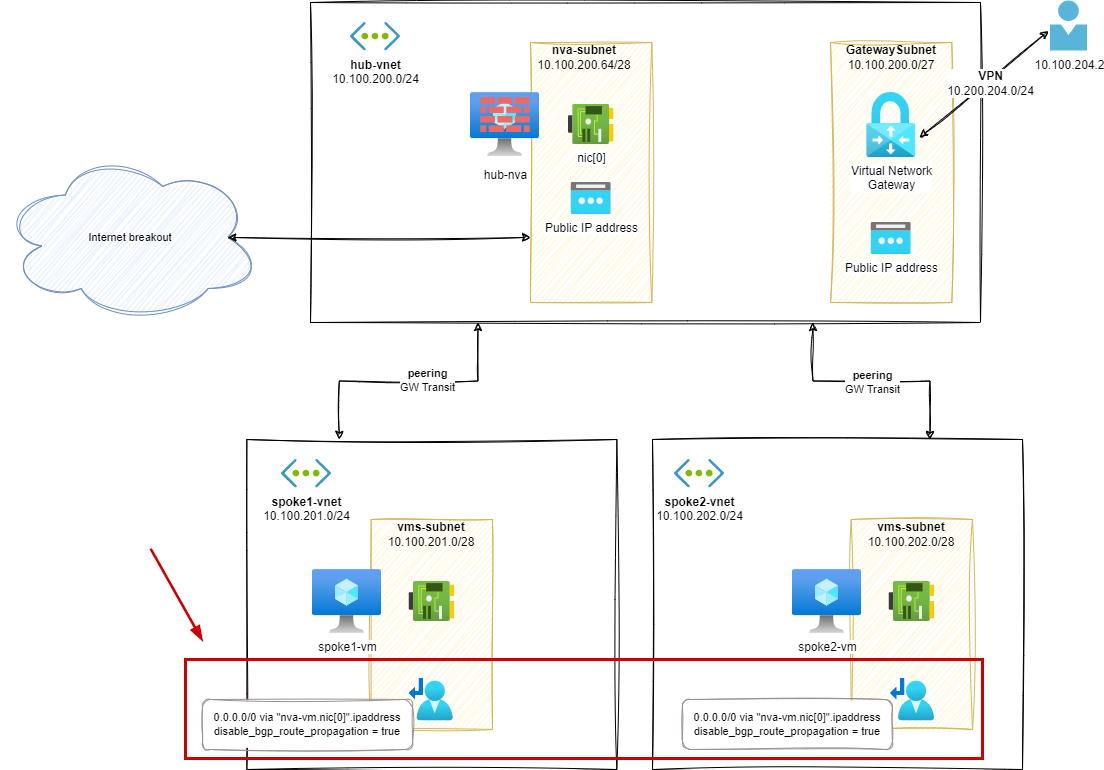
In this stage, we will add a UDR on spoke1-vnet and spoke2-vnet to enable communication between spokes.
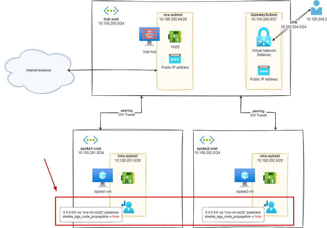
For each spoke subnet, we will add a UDR with the following configuration:
- 0.0.0.0/0 via
nva-vm.nic[0].ipaddress disable_bgp_route_propagation = false
From UI, it looks like this:
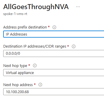
The next hop address is the IP address of the hub-nva VM NIC in the hub-vnet.
We also setup the following Gateway route propagation configuration:
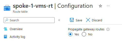
You may notice a difference in wording between Azure UI and Terraform regarding Gateway route propagation setting. In Azure UI, the option is called Propagate gateway route. In API based tools like Terraform, Bicep and ARM, the option is called disableBgpRoutePropagation (ARM/Bicep) or disable_bgp_route_propagation (Terraform).
This can be confusing when related to boolean values. In this case, false means that the routes from Gateway components will be propagated to the subnets associated with the UDR.
Routes analysis (s2)
Effective routes on spoke-1-vm.nic[0]:
1az network nic show-effective-route-table --ids /subscriptions/<sub-id>/resourceGroups/nva-testing-RG/providers/Microsoft.Network/networkInterfaces/spoke-1-vnet-vm-nic -o table
2# output
3Source                 State    Address Prefix    Next Hop Type          Next Hop IP
4---------------------  -------  ----------------  ---------------------  -------------
5Default                Active   10.100.201.0/24   VnetLocal
6Default                Active   10.100.200.0/24   VNetPeering
7VirtualNetworkGateway  Active   10.100.204.0/24   VirtualNetworkGateway  20.16.121.157
8Default                Invalid  0.0.0.0/0         Internet
9User                   Active   0.0.0.0/0         VirtualAppliance       10.100.200.68 # <--- via hub-nva
![Effective routes on spoke-1-vm.nic[0]](https://vuptime.io/images/avs-nva/stage2/effectives-routes-spoke-1-vm.png)
VM on different spokes can communicate together: Example, from spoke-1-vm to spoke-2-vm:
 1ubuntu@spoke-1-vnet-vm:~$ ping 10.100.202.4 -c3
 2# output
 3PING 10.100.202.4 (10.100.202.4) 56(84) bytes of data.
 464 bytes from 10.100.202.4: icmp_seq=1 ttl=63 time=4.05 ms
 564 bytes from 10.100.202.4: icmp_seq=2 ttl=63 time=1.59 ms
 664 bytes from 10.100.202.4: icmp_seq=3 ttl=63 time=2.18 ms
 7
 8-- - 10.100.202.4 ping statistics ---
 93 packets transmitted, 3 received, 0% packet loss, time 2001ms
10rtt min/avg/max/mdev = 1.587/2.604/4.049/1.049 ms
From the hub-nva VM, we can see the traffic going through:
1IP 10.100.201.4 > 10.100.202.4: ICMP echo request, id 8, seq 1, length 64
2IP 10.100.200.68 > 10.100.202.4: ICMP echo request, id 8, seq 1, length 64
3IP 10.100.202.4 > 10.100.200.68: ICMP echo reply, id 8, seq 1, length 64
4IP 10.100.202.4 > 10.100.201.4: ICMP echo reply, id 8, seq 1, length 6
From a VPN connection we can reach spoke resources:
1ubuntu@vpn-client:~$ ping 10.100.201.4 -c3
2# output
3PING 10.100.201.4 (10.100.201.4) 56(84) bytes of data.
464 bytes from 10.100.201.4: icmp_seq=1 ttl=63 time=24.1 ms
564 bytes from 10.100.201.4: icmp_seq=2 ttl=63 time=22.7 ms
664 bytes from 10.100.201.4: icmp_seq=3 ttl=63 time=24.9 ms
But… if we look from the hub-nva VM, there is no match for this network traffic. Meaning that the traffic is, as we can guess from the effective routes tables on spokes VMs, going directly from spokes VMs to the VPN Gateway and vice&versa.
We will try to mitigate this in the next steps by forcing the traffic to go through the hub-nva VM.
Additional information about Azure UDR
If you need to learn more about UDR in Azure, I strongly recommend you to read the following posts:
- User Defined Routes in Azure documentation
- How Azure selects a route in Azure documentation
- Don’t let your Azure Routes bite you by Jose Moreno
Stage 3 – User Defined Route on spokes / GW propagation false
In this stage, we will start mitigating the issue we have in the previous stage about the network traffic, related to VPN, bypassing our NVA device.
The first thing we can try is to disable Gateway route propagation on the UDRs we have created in the previous stage.
For each spoke subnet, we will add a UDR with the following configuration:
- 0.0.0.0/0 via
nva-vm.nic[0].ipaddress disable_bgp_route_propagation = true
From UI, it looks like this:
As mentioned earlier, if you use an automation tool to setup this configuration value, you will notice a confusing wording. In Azure UI, the option is called Propagate gateway route. In API based tools like Terraform, Bicep and ARM, the option is called disableBgpRoutePropagation (ARM/Bicep) or disable_bgp_route_propagation (Terraform).
In this case, true means that the routes from Gateway components will not be propagated to the subnets associated with the UDR.
Routes analysis (s3)
Effective routes on spoke-1-vm.nic[0]:
 1az network nic show-effective-route-table \
 2    --ids /subscriptions/<sub-id>/resourceGroups/nva-testing-RG/providers/Microsoft.Network/networkInterfaces/spoke-1-vnet-vm-nic \
 3    -o table
 4# output
 5Source    State    Address Prefix    Next Hop Type     Next Hop IP
 6--------  ------ - ----------------  ----------------  ------------ -
 7Default   Active   10.100.201.0/24   VnetLocal
 8Default   Active   10.100.200.0/24   VNetPeering
 9Default   Invalid  0.0.0.0/0         Internet
10User      Active   0.0.0.0/0         VirtualAppliance  10.100.200.68 # <--- via hub-nva
![Effective routes on spoke-1-vm.nic[0]](https://vuptime.io/images/avs-nva/stage3/effectives-routes-spoke-1-vm.png)
According to the new UDR setting: The route to the VPN subnet is no more directly published in the effective routes for spoke-1-vm NIC.
If spoke-1-vm need to communicate with a VPN based resource, the default 0/0 path will be used, going through the hub-nva VM.
If we try a ping from VPN client to spoke-1-vm, it works…
 1ubuntu@vpn-client:~$ ping 10.100.201.4 -c3
 2# output
 3PING 10.100.201.4 (10.100.201.4) 56(84) bytes of data.
 464 bytes from 10.100.201.4: icmp_seq=1 ttl=62 time=23.6 ms
 564 bytes from 10.100.201.4: icmp_seq=2 ttl=62 time=48.0 ms
 664 bytes from 10.100.201.4: icmp_seq=3 ttl=62 time=64.1 ms
 7
 8-- - 10.100.201.4 ping statistics ---
 93 packets transmitted, 3 received, 0% packet loss, time 2001ms
10rtt min/avg/max/mdev = 23.609/45.235/64.094/16.643 ms
… but, there is a glitch in the Matrix:
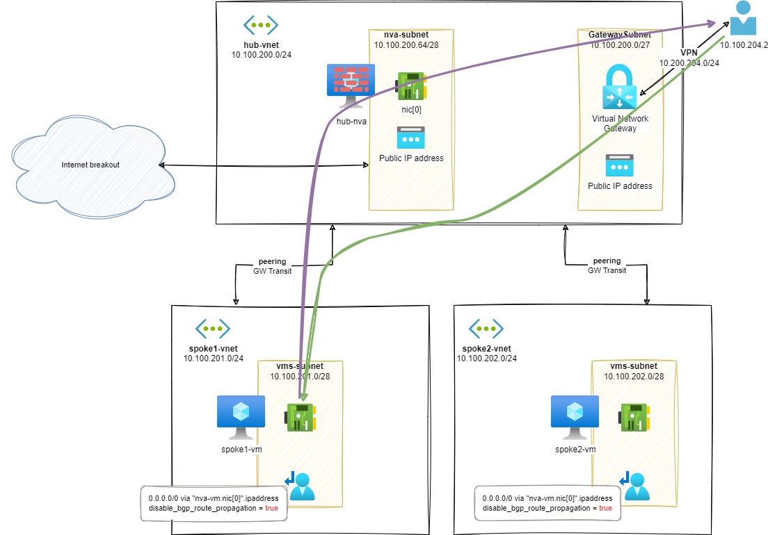
As you can see, only the traffic from spoke-1-vm to VPN is going through the hub-nva. On the contrary, traffic from VPN clients is going directly to spoke VMs resulting in an asymmetric network pattern.
For example, when doing a ping from VPN client to spoke-1-vm, we can only see echo reply going through the hub-nva when doing a tcpdump:
1ubuntu@hub-nva:~$ sudo tcpdump -nni eth0  icmp
2# output
3IP 10.100.201.4 > 10.100.200.68: ICMP echo reply, id 1002, seq 1, length 64
4IP 10.100.201.4 > 10.100.204.2: ICMP echo reply, id 1002, seq 1, length 64
The echo request is missing: the flow from VPN client is not passing through the hub-nva.
Additional information about Gateway route propagation
If you are interested in more details about the Gateway route propagation feature, you can refer to the following posts:
- Border gateway protocol in the Azure documentation
- Virtual Network Gateways routing in Azure by Jose Moreno
- Connectivity impact of adding a Virtual Network Gateway (ER or VPN) by Cynthia Treger
Part 1 – Conclusion
In the previous stages, we have seen how to initialize a hub and spoke topology within Azure. At the current stage, our Azure hosted spokes vNet are using the hub vNet as a transit network, leveraging on the default route configured on User Defined Routes (UDR).
Regarding the VPN connectivity (acting as On Premises workloads), we have discovered that we are facing an asymmetric routing issue. Traffic from VPN clients to Azure hosted VMs is not going through the NVA VM deployed in the hub vNet.
As a reminder, you can leverage on the content of the following GitHub repository to reproduce the steps described in this post: hub-and-spoke-avs-transit-step-by-step.
In the next post, we will see how to mitigate this issue by leveraging on a new User Defined Route configuration. We will also introduce the connectivity of Azure VMware Solution (AVS) to this hub and spoke topology.