Third-party firewall NVA in Azure VMware Solution NSX-T deployment
Overview
In a previous series of blog posts (posts: 1, 2 & 3), we covered the deployment of a third-party firewall Network Virtual Appliance (NVA) in Azure to integrate an Azure VMware Solution (AVS) deployment in a Hub&Spoke network topology. This setup enable traffic filtering for ingress and egress traffic to and from the AVS environment (N/S) but do not provide any filtering between AVS workloads (E/W). The recommended way to achieve this is to rely on the NSX-T distributed firewall capabilities.
In this blog post, we will cover the deployment of a third-party firewall NVA in an AVS SDDC itself to provide traffic filtering between AVS workloads without relying on the NSX-T distributed firewall capabilities.
I will not discuss here the reasons to deploy a 3rd firewall NVA in AVS SDDC. I will just mention that this is a common request from customers that want to continue using the same firewall technology in AVS that they have been using for an on-premises datacenter.
This topic was also covered by several colleagues of mine in previous blog posts:
- Third-party firewall NVA in Azure VMware Solution by Amit Aneja (Microsoft).
- Third Party Firewalls in AVS by Kenyon Hensler (Microsoft).
- Azure VMware Solution: Connecting 3rd Party Networking and Security Platforms By: Gourav Bhardwaj (VMware), Trevor Davis (Microsoft) and Jeffrey Moore (VMware).
I will try to provide some details to help in the deployment of a such solution.
Default AVS topology
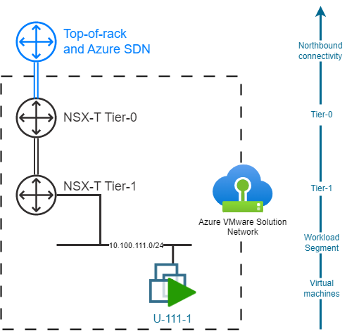
By default, an AVS SDDC is deployed with preprovisioned NSX-T Tier-0 and Tier-1 Gateways. The Tier-0 Gateway is used to connect the AVS SDDC to Top-of-rack and Azure SDN, and is fully Microsoft-managed. The default Tier-1 Gateway can be used to deploy network segments and is customer-managed. Customers can also create more Tier-1 Gateways if needed.
Challenges of inserting a third-party firewall NVA in AVS SDDC
The first limit to understand with 3rd party NVA insertion in AVS SDDC is that it is not possible to rely on NSX-T Service Insertion capabilities. This limit is mostly driven by the "managed" nature of Azure VMware Solution.
A second limit to consider it that 3rd party NVA deployed in the AVS SDDC are limited by the number of virtual network interfaces that can be attached to a single VM. With only 10 NICs available per Virtual Machine, it is not possible to directly connect an NVA to a deployment with more than 9 workload segments.
A possible mitigation is to use a Transit Segment. This Transit Segment will be connected to additional Tier-1 Gateway and will be used to route traffic between the NVA and the workload segments via additional Tier-1 Gateways. In this topology, the new limit will be based on the maximum number of Tier-1 Gateways that can be deployed in an AVS SDDC and/or the size of the transit subnet address plan. This enables provisioning 100s of workload segments if needed.
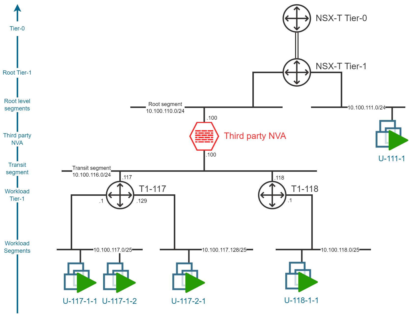
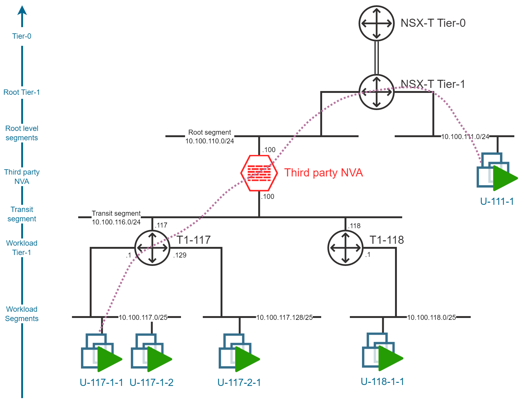
Layered network topology
In order to deploy a third-party firewall NVA in an AVS SDDC, we will need to deploy a layered network topology. This topology will be composed of 3 layers:
- A Root-segment, connected to the first layer of Tier-1 gateway (like the one deployed by default) and to the NVA uplink.
- One or more Transit-segment, connected to the NVA downlink(s) and a second layer of Tier-1 gateways
- Workload-segments where the Virtual Machines will be deployed.
Transit-segment or Transit-segments
There are two possible strategies regarding the number of Transit-segment to deploy:
- Using multiple Transit-segments enable to deploy up to 8 additional Tier-1 gateways. Each Tier-1 gateway can be link to up to 1000 workload segments.
- This setup will provide scalability but the segments attached to a single Tier-1 gateway will not go through the NVA to communicate with each other.
- This setup can be more complex to maintain and will have scalability limit if E/W traffic filtering at NVA level, is required.
- Using a single Transit-segment enable the deployment of more Tier-1 gateways (100s) and to dedicate 1 Tier-1 gateway per workload segment.
- This "1 Tier-1 gateway per workload segment" setup will mitigate the issue mentioned above regarding the filtering of E/W traffic.
- This setup may also introduce security concerns to consider as the one mentioned in the Security recommendations section.
- Scalability is limited to Transit subnet size: a proper planning is required to not run out of IP addresses.
Note: In this blog post, I will try to illustrate the two strategies.
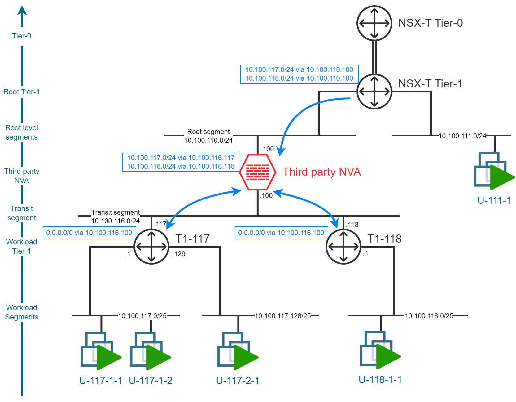
Static routes
In order to route traffic between the different segments, we will need to configure static routes in the Tier-1 Gateways. The following table provides an overview of the static routes that will need to be configured in the Tier-1 Gateways.
| Gateway/Device | Route | Next Hop |
|---|---|---|
| Root Tier-1 | workload segments | NVA |
| Workload Tier-1s | default route (0/0) | NVA |
| NVA | workload segments | Workload Tier-1 |
Here is an example, applied to my lab environment:
Traffic flow analysis
Intra-segment traffic
As you may already imagine, the traffic flow for Virtual Machines deployed in the same workload segment will not be impacted by the NVA insertion. The traffic will be routed directly between the Virtual Machines at the L2 level.
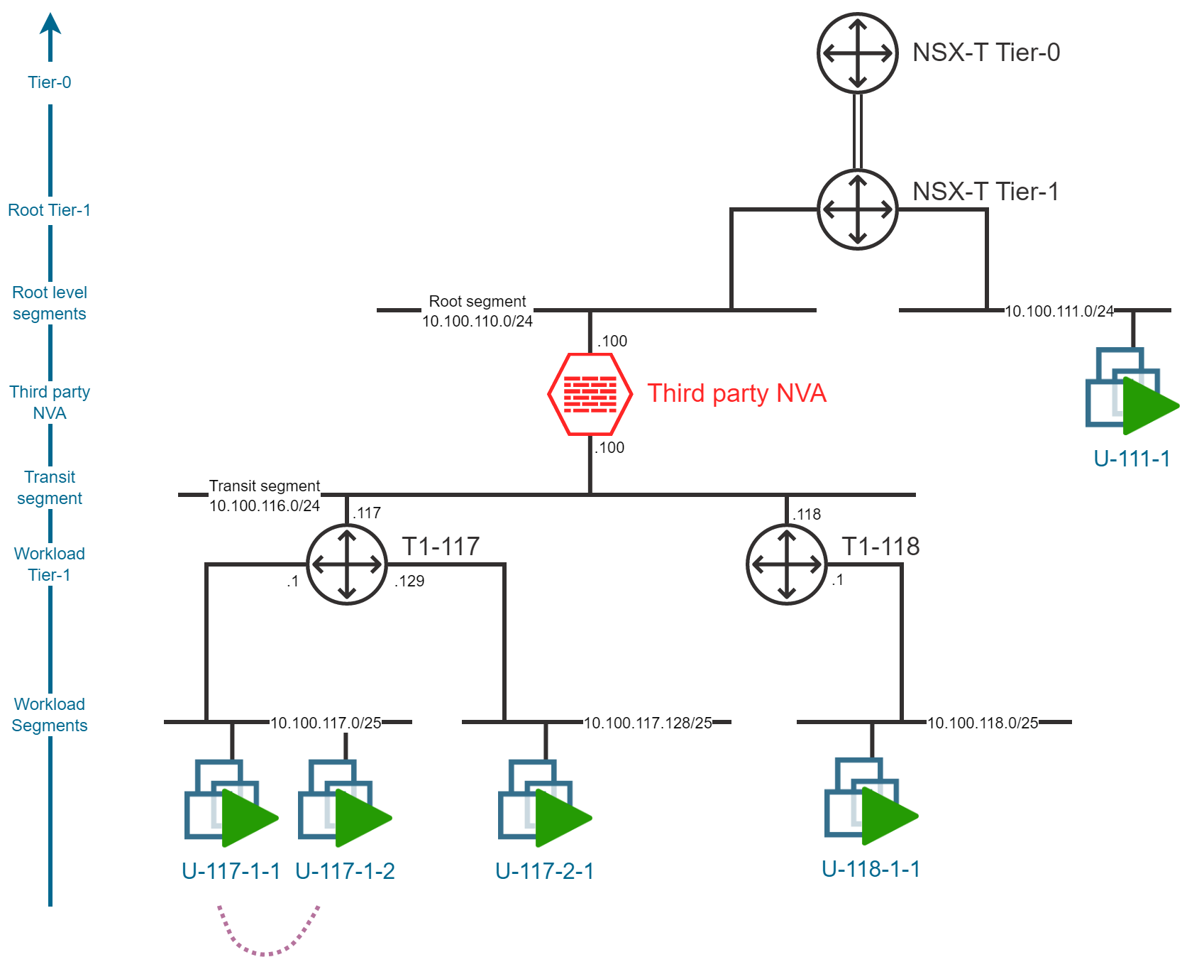
Note: Still it is possible to filter the traffic between the Virtual Machines in the same segment by leveraging on the NSX-T Distributed Firewall capabilities.
East-West, Inter-segment traffic, same Tier-1
The traffic flow between Virtual Machines deployed in different workload segments connected to the same Tier-1 Gateway will also, not be impacted by the NVA insertion and the traffic will only pass through the Tier-1 gateway.

To filter this kind of network traffic, you can either rely on the NSX-T Distributed Firewall or Gateway Firewall capabilities.
East-West, Inter-segment traffic, different Tier-1
The traffic flow between Virtual Machines deployed in different workload segments connected to different Tier-1 Gateways will be impacted by the NVA insertion. The traffic will be routed via the NVA and the Tier-1 Gateways.

This is the most representative configuration of the traffic flow that we want to achieve with the NVA insertion.
In order to generalize this configuration, we will need to deploy a Tier-1 Gateway per workload segment.
North-South traffic
North-South traffic will also be impacted by the NVA insertion. The traffic will be routed via the NVA to reach all the targets on the north-side of the NVA. Either Virtual Machines deployed directly on the south-side of the default Tier-0/Tier-1 Gateways or other targets reachable via the default Tier-0/Tier-1 Gateways like:
- Azure based resources
- On-premises resources via ExpressRoute or VPN
- Internet
Other considerations
Security recommendations
With multiple routing devices (Tier-1 gateways) deployed behind the NVA, it is important to ensure that the NVA is not bypassed by the traffic. It is recommended to consider blocking ICMP redirects at the distributed firewall level and to configure the NVA to:
- Ignore ICMP redirects
- Not send ICMP redirects
Introducing new static routes may also lead to traffic routing bypassing the NVA. It is important to ensure a proper configuration of the static routes in the Tier-1 Gateways.
NVA high availability
Here I only demonstrated the capacity to architect and organize traffic flow, to be filtered by a single NVA instance. In a production environment, it is important to consider the high availability of the NVA. This can be achieved by deploying multiple NVA instances and consider VRRP (Virtual Router Redundancy Protocol) grouping and load-balancing to ensure the high availability of the NVA.
Known limitations
A well-known limitation of this design topology is about HCX and the Mobility Optimized Network (MON) were the behavior can be hard to predict. This is a reason Mobility Optimized Network is not supported by Microsoft in AVS with a third party NVA setup.